



News
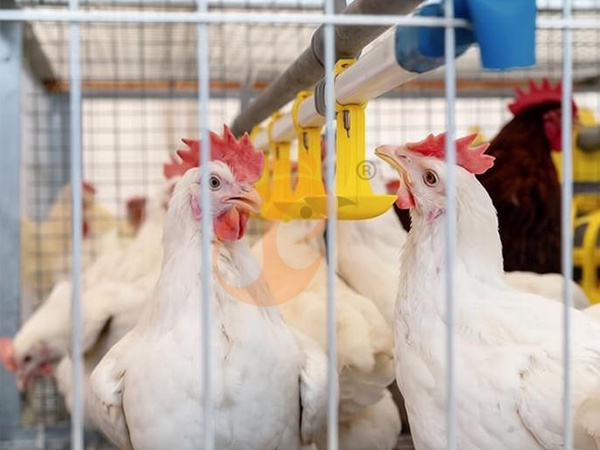
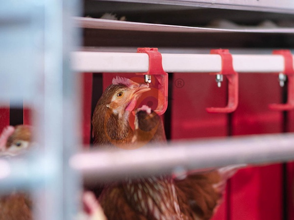
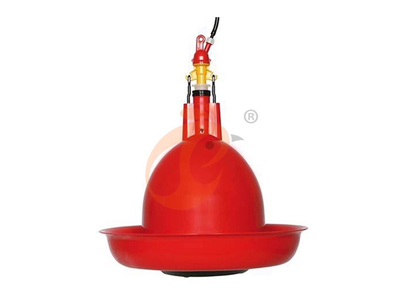
Water flow stability in nipple drinkers is essential for modern poultry production efficiency and animal hydration performance.
Hydraulic pressure regulation determines consistent water discharge across long pipeline distribution systems.
Mechanical valve design influences response accuracy and long term operational durability in drinker assemblies.
Filtration and water quality management reduce contamination risk and maintain internal system cleanliness standards.
Installation geometry and system diagnostics support uniform flow behavior and early fault detection in water networks.
Get professional poultry farm construction guidance, equipment selection solutions, and the latest price lists, whatsApp to +8618830120193, click to learn more:
Hydraulic Stability Through Pressure Calibration
Nipple drinker systems depend on stable hydraulic pressure to maintain consistent valve response across distributed pipelines.
Pressure variation directly influences discharge behavior and mechanical actuation timing.
Data is for reference only.Swipe horizontally to view full table.
Hydraulic equilibrium ensures uniform valve activation across long production lines.
Pressure regulators maintain system balance under fluctuating demand conditions.
Installation calibration prevents localized overpressure or underpressure zones in pipelines.
Pipeline Geometry And Internal Flow Resistance
Pipeline design determines friction loss and flow velocity distribution inside nipple drinking systems.
Diameter selection influences Reynolds number behavior and energy dissipation levels.
Data is for reference only.Swipe horizontally to view full table.
Pipeline optimization improves uniform water delivery across extended poultry housing systems.
Friction reduction enhances responsiveness of downstream nipple valves.
Geometric alignment ensures balanced hydraulic distribution across multiple sections.
Filtration And Contaminant Control
Filtration systems prevent particulate intrusion into sensitive nipple valve assemblies.
Contaminant size control is essential for maintaining valve sealing integrity.
Data is for reference only.Swipe horizontally to view full table.
Filtration efficiency stabilizes internal pipeline cleanliness over extended operation cycles.
Particle control reduces mechanical wear inside valve assemblies.
Consistent filtration improves long term hydraulic system reliability.
Water Demand Synchronization With Growth Curve
Water consumption varies significantly according to biological growth stages in poultry production.
Accurate demand estimation prevents hydraulic overload and system inefficiency.
Data is for reference only.Swipe horizontally to view full table.
Water demand tracking ensures balanced hydraulic supply across production cycles.
Consumption variation reflects metabolic changes in livestock development phases.
System design must accommodate peak demand periods without pressure collapse.
Mechanical Response Of Nipple Valve Assembly
Valve assemblies convert hydraulic pressure into mechanical displacement for controlled water release.
Component wear affects actuation force and cycle stability over time.
Data is for reference only.Swipe horizontally to view full table.
Mechanical precision ensures consistent water release across repeated actuation cycles.
Component fatigue gradually modifies hydraulic response behavior.
Material selection influences long term durability under continuous operation conditions.
Chemical Cleaning Concentrations And Biofilm Removal
Chemical cleaning controls microbial accumulation inside pipeline systems.
Dosage accuracy ensures compatibility with metallic and polymer components.
Data is for reference only.Swipe horizontally to view full table.
Chemical treatment maintains internal hygiene across long pipeline networks.
Biofilm reduction improves hydraulic flow consistency in nipple systems.
Residue monitoring ensures complete flushing after cleaning cycles.
Pump Performance And Energy Efficiency
Pump systems regulate pressure distribution across nipple drinker pipelines.
Energy efficiency reflects hydraulic load balance and mechanical wear conditions.
Data is for reference only.Swipe horizontally to view full table.
Pump optimization stabilizes pressure delivery across distributed hydraulic networks.
Energy consumption reflects system resistance and operational load conditions.
Variable speed control improves hydraulic adaptability under fluctuating demand cycles.
System Diagnostics And Hydraulic Behavior Mapping
Diagnostic systems translate physical symptoms into hydraulic performance indicators.
Early detection improves maintenance scheduling and operational stability.
Data is for reference only.Swipe horizontally to view full table.
Diagnostic mapping improves predictive maintenance efficiency across drinking systems.
Hydraulic deviation tracking identifies early stage mechanical degradation.
System monitoring reduces unexpected downtime in production environments.
Frequently Asked Questions
Q1: What pressure range ensures stable nipple drinker flow?
Stable operation typically occurs within 0.18 to 0.55 bar depending on livestock category.
Deviation beyond 0.10 bar often results in inconsistent valve response across pipelines.
Pressure calibration must align with elevation head and pipeline length conditions.
Q2: How often should pipeline cleaning be performed?
Cleaning cycles depend on water quality and system load conditions.
Typical operational schedules range from 10 to 40 minutes per chemical cycle exposure.
Residual conductivity below 250 µS/cm indicates effective flushing completion.
Q3: What causes uneven water distribution in long pipeline systems?
Uneven distribution often results from pressure loss between 1.4 and 6.2 kPa per 10 meters.
Pipeline diameter mismatch and air accumulation contribute to hydraulic imbalance.
Correct leveling and venting reduce flow inconsistency across sections.
Taiyu (HK) Group - One Of China Biggest Nipple Drinkers Manufacturer
Nipple drinker systems designed for poultry hydraulic control and precision water delivery.
Global factory direct supply supporting integrated poultry equipment production networks.
Turn-key engineering solutions covering farm water line installation and system design.
Export focused manufacturing with standardized hydraulic and filtration system components.
Large scale production capacity supporting customized agricultural drinking system projects.
Contact Us To Received Your Customized Poultry Farm Plan
Headquarters And Branchs
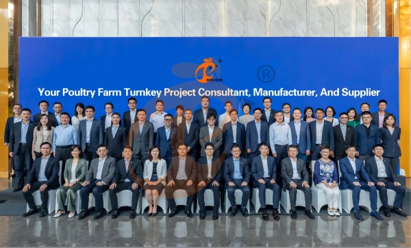
Hong Kong Headquarter Management Team
Hong Kong Headquarter Taiyu Industrial Group CO., LTD
China Hebei Best Machinery And Equipment CO., LTD
Nigeria Vanke Machinery And Equipment CO., LTD
Tanzania Best Machinery And Equipment CO., LTD
Ethiopia Best Hebei Machinery Manufacturing PLC
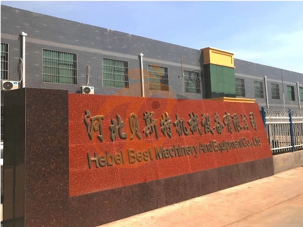
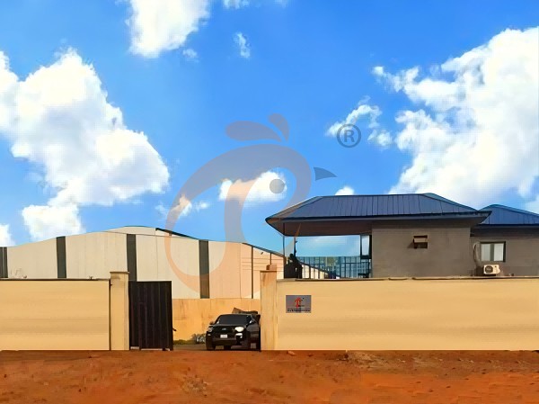
Reception /24 WhatsApp NO. : +8618830120193
FAQ
What Water Quality Requirements Are Necessary For Nipple Drinkers In Poultry Chicken Cage Systems?
Water hardness is maintained within 100–150 mg/L CaCO₃ equivalent for valve protection.
Microbial load is controlled under 100 CFU/mL for safe poultry consumption standards.
What Is The Recommended Stocking Ratio For Nipple Drinkers In Poultry Chicken Cage Systems?
Drinker spacing is typically set at 25–30 cm to reduce competition stress.
Water demand allocation is calculated at 180–220 ml per bird daily in intensive production.
How Is Water Flow Regulated In Nipple Drinkers For Poultry Chicken Cage Farming Systems?
Pressure stability is maintained within 0.18–0.22 MPa across drinking lines.
Drop formation interval is adjusted at 1–2 seconds per activation for efficient intake.
Product Recommendations
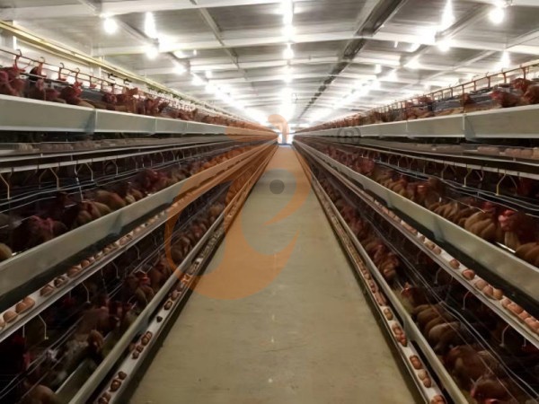
 Imported Vs Local H Type Chicken Battery Cages: Which Offers Better Quality?1. H Type Chicken Battery Cage layouts require coordinated house dimensions
2. Multi-tier cage structures support organized commercial layer production
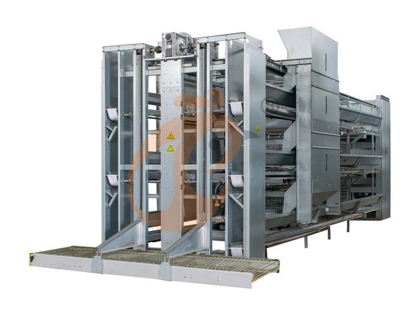
3. Automatic systems connect feeding, drinking, manure, and egg handling
4. Engineering drawings define interfaces before equipment manufacturing begins
5. Reception /WhatsApp NO. : +8618830120193Read more A Type Battery Cage For Layers Vs Broilers: Which System Is More Suitable?1. A Type Battery Cage requires coordinated structural and utility planning
2. Layer housing layouts determine equipment positioning and service access
3. Automatic feeding reduces repetitive manual feed distribution work
4. Manure handling requires suitable conveyor or scraper interfaces
5. Reception /WhatsApp NO. : +8618830120193Read more 5 Practical Methods To Reduce Noise From Pralson Feeders1. Pralson feeders connect feed delivery with mechanical alignment requirements
2. Poultry houses require coordinated suspension and drive arrangements
3. Noise inspection should follow measurable mechanical checkpoints
4. Feeding performance depends on compatible component configuration
5. Reception /WhatsApp NO. : +8618830120193Read more Deep Litter System For Broiler Chickens | 7 Daily Checks1. Deep litter management depends on coordinated ventilation and drinking equipment
2. Daily inspections connect measurable house conditions with equipment operation
3. Feeding, water, airflow, and automation should follow synchronized procedures
4. Equipment specifications should match building dimensions and flock capacity
5. Reception /WhatsApp NO. : +8618830120193Read more Free Range System For Broiler Chickens | 7 Daily Management Checks1. Free-range houses require coordinated feed and water distribution systems with defined equipment layouts
2. Ventilation settings should reflect outdoor temperature and house dimensions through controller-based adjustments
3. Automatic doors require reliable scheduling and mechanical inspection procedures for consistent daily access
4. Daily records support preventive maintenance and equipment troubleshooting across interconnected farm systems
5. Reception /WhatsApp NO. : +8618830120193Read more Standard Vs Custom Broiler Chicken Cage Systems | Which Fits Your Farm?1. Standard cage systems use established component dimensions for conventional poultry houses.
2. Custom cage systems adapt equipment arrangements to actual building geometry and operating requirements.
3. Feeding and drinking equipment should be coordinated with cage placement during engineering.
4. Manure removal equipment should be planned before final equipment installation.
5. Reception /WhatsApp NO. : +8618830120193Read more Broiler Chicken Cage For Sale | 5 Key Factors Buyers Must Check1. Cage layouts require accurate building dimensions before equipment configuration begins
2. Feeding circuits should align with row lengths and service passages
3. Water systems need filtration and pressure control before commissioning
4. Manure conveyors require accessible inspection points for routine maintenance
5. Reception /WhatsApp NO. : +8618830120193Read more Nipple Drinker With Cup Vs Without Cup | Which Reduces Spillage?1. Nipple systems maintain consistent water access during poultry production stages
2. Cup designs help manage moisture around drinking locations effectively
3. Farm layouts influence equipment selection and installation methods
4. Different bird categories require suitable drinking system configurations
5. Reception /WhatsApp NO. : +8618830120193Read more Pellet Machine Energy Saving | 6 Effective Techniques1. Pelletizing efficiency depends on coordinated material preparation and conditioning
2. Stable feeding reduces unnecessary load fluctuations during production
3. Die and roller maintenance supports consistent mechanical compression
4. Cooling and screening protect finished pellet quality after compression
5. Reception /WhatsApp NO. : +8618830120193Read more Deep Litter Broiler System Investment Guide | 5 Decision Tips1. Deep litter housing requires accurate equipment positioning before installation
2. Ventilation calculations should match house volume and climate conditions
3. Feeding lines require progressive height adjustment during bird growth
4. Water systems need filtration and pressure control for stable delivery
5. Reception /WhatsApp NO. : +8618830120193Read more Free Range Broiler System Investment Guide | 5 Decision Tips1. Free-range broiler housing requires coordinated indoor production management
2. Automatic feeding reduces routine manual feed distribution work
3. Ventilation design depends on house volume and climate
4. Nipple drinking requires controlled pressure and regular inspection
5. Reception /WhatsApp NO. : +8618830120193Read more Floor Rearing Broiler Farming Profit | 6 Key Factors Explained1. Floor rearing systems require coordinated airflow and feeding equipment
2. Broiler houses need consistent water access throughout cycles
3. Environmental sensors provide measurable operating conditions for controllers
4. Maintenance schedules help prevent equipment-related production interruptions
5. Reception /WhatsApp NO. : +8618830120193Read more Turnkey Poultry Equipment Investment | 5 Practical Decision Tips1. Commercial poultry layouts require coordinated equipment positioning
2. Ventilation calculations should precede final equipment quantities
3. Feeding systems require compatible electrical and mechanical interfaces
4. Climate conditions influence cooling and airflow configuration
5. Reception /WhatsApp NO. : +8618830120193Read more Battery Cage For Layers ROI | 5 Practical Profit Analysis Tips1. Battery Cage For Layers layouts require coordinated structural and ventilation calculations
2. Layer cage system dimensions should match building geometry and service access
3. Automatic layer cage system integration depends on compatible mechanical and electrical interfaces
4. Commercial poultry equipment planning should separate capital costs from recurring operating expenses
5. Reception /WhatsApp NO. : +8618830120193Read more Broiler Chicken Cage ROI | 5 Practical Profit Analysis Tips For Investors1. Broiler Chicken Cage layouts depend on actual building dimensions and structure
2. Feed system sizing should follow required production throughput calculations
3. Ventilation specifications should reflect house volume and climate conditions
4. Manure equipment selection should consider line length and drive capacity
5. Reception /WhatsApp NO. : +8618830120193Read more 7 Ways To Prevent Pellet Machine Blockages Quickly1. Pellet machines convert prepared feed into uniform compact pellets
2. Stable feeding supports consistent compression throughout production
3. Conditioning improves material flow before pelletizing begins
4. Die selection connects formulation requirements with pellet dimensions
5. Reception /WhatsApp NO. : +8618830120193Read more A Type Poultry Cage Vs Floor Rearing System: 5 Performance Comparisons1. A Type poultry cage layouts determine equipment positions and maintenance access
2. Feed distribution requires coordinated drive systems and suitable delivery routes
3. Manure removal depends on belt dimensions, motor selection, and discharge planning
4. Environmental controls connect sensors, ventilation equipment, and house conditions
5. Reception /WhatsApp NO. : +8618830120193Read more Poultry Equipment Supplier | 5 Practical Tips To Choose The Right One1. Poultry equipment selection depends on house dimensions and flock capacity
2. Ventilation planning should account for climate and building structure
3. Feeding systems require coordinated capacity calculations before installation
4. Water systems require filtration and pressure checks before commissioning
5. Reception /WhatsApp NO. : +8618830120193Read more Battery Cage For Layers Cost | 6 Key Factors Affecting Price1. Layer cages organize birds vertically within dedicated housing rows
2. Feeding systems distribute feed consistently across cage sections
3. Manure equipment transfers waste toward designated collection areas
4. Water systems regulate drinking supply throughout production rows
5. Reception /WhatsApp NO. : +8618830120193Read more Broiler Chicken Cage Cost | 6 Key Factors Affecting Price And Budget1. Broiler cage projects require coordinated structural and mechanical specifications
2. House dimensions determine cage rows and equipment placement
3. Feeding and drinking systems require compatible connection layouts
4. Environmental systems depend on ventilation and cooling requirements
5. Reception /WhatsApp NO. : +8618830120193Read more How To Maximize Water Efficiency With Nipple Drinkers | 6 Tips1. Nipple drinkers provide controlled water delivery for poultry
2. Pressure regulation supports stable drinking-line operation
3. Filtration helps protect internal nipple components
4. Scheduled flushing removes accumulated line contaminants
5. Reception /WhatsApp NO. : +8618830120193Read more How To Upgrade Pellet Machines | 6 Practical Strategies1. Pelletizing performance depends on coordinated material preparation and mechanical compression
2. Feed moisture and particle size directly influence forming stability
3. Cooling and screening determine finished-product handling characteristics
4. Equipment interfaces should be planned before installation begins
5. Reception /WhatsApp NO. : +8618830120193Read more Poultry Cage Cost Per Bird Vs Total Project Cost: 5 Smart Comparisons1. Poultry cage layouts require accurate building dimensions before equipment production
2. Cage capacity calculations depend on selected housing configuration and tiers
3. Equipment routes should maintain accessible maintenance and service clearance
4. Electrical specifications must match local power infrastructure and motors
5. Reception /WhatsApp NO. : +8618830120193Read more Which H Type Chicken Cage Design Is Best For 20,000+ Layer Poultry Farms?1. H type chicken cage layouts require accurate building dimensions for equipment coordination
2. Automatic feeding routes should align with cage rows and service passages
3. Manure systems require planned access for inspection and scheduled maintenance
4. Egg collection equipment should connect cage rows with central transfer points
5. Reception /WhatsApp NO. : +8618830120193Read more Is Deep Litter System Suitable For Broilers? | 5 Answers1. Proper poultry farming requires stable environmental control mechanisms
2. Modern equipment ensures high animal welfare standards
3. Quality management systems reduce disease risks significantly
4. Reliable automation optimizes feed conversion efficiency daily
5. Reception /WhatsApp NO. : +8618830120193Read more Is Free Range System Suitable For Broilers? | 5 Practical Answers1. Free range broiler houses combine indoor control with outdoor access
2. Feeding equipment maintains predictable daily feed distribution
3. Drinking systems support continuous access to clean water
4. Ventilation equipment manages changing indoor environmental conditions
5. Reception /WhatsApp NO. : +8618830120193Read more Floor Rearing System For Broiler Chickens | 5 Daily Management Checks1. Floor rearing systems require coordinated equipment layouts
2. Feeding lines should align with house dimensions and flock capacity
3. Water systems require filtration, regulation, distribution, and flushing
4. Ventilation systems depend on airflow calculations and building structure
5. Reception /WhatsApp NO. : +8618830120193Read more How To Reduce Operating Costs With Poultry Equipment | 6 Tips1. Feed distribution accuracy supports controlled material allocation across poultry houses
2. Environmental sensors provide continuous measurements for automated equipment adjustment
3. Water monitoring helps identify abnormal consumption and potential system leakage
4. Preventive inspection supports mechanical reliability throughout equipment operating cycles
5. Reception /WhatsApp NO. : +8618830120193Read more A Type Battery Cage Vs Cage-Free System: Which Is More Profitable For Layers?1. A Type Battery Cage layouts require accurate building dimensions before equipment quantities are calculated
2. Feeding systems should align drive capacity with planned row lengths
3. Egg conveyors require coordinated transfer heights between housing and packing areas
4. Manure systems should match belt length, discharge direction, and removal cycles
5. Reception /WhatsApp NO. : +8618830120193Read more Floor Rearing Broiler House Design | 6 Practical Layout Guidelines1. Floor plans should maintain unobstructed routes between production zones and equipment access points
2. Feeder suspension should allow adjustment throughout broiler growth cycles
3. Water pipelines require accessible filtration and pressure-control positions
4. Ventilation components should align with calculated airflow paths and house geometry
5. Reception /WhatsApp NO. : +8618830120193Read more Nipple Drinker System Design | 5 Key Planning Tips For Farms1. Nipple lines require coordinated hydraulic planning across pressure, filtration, flushing, and suspension components
2. Bird access depends on correct drinking-line positioning throughout each production stage
3. Water quality should be evaluated before finalizing filtration and treatment equipment
4. Pipeline design should provide practical access for inspection and routine cleaning
5. Reception /WhatsApp NO. : +8618830120193Read more 7 Ways To Reduce Maintenance Costs For Pralson Feeders1. Pralson Feeders maintenance depends on correct installation and scheduled inspection
2. Automatic feeding lines require coordinated mechanical and electrical checks
3. Feed residue management supports consistent equipment operating conditions
4. Component records simplify replacement planning across production cycles
5. Reception /WhatsApp NO. : +8618830120193Read more 6 Practical Tips To Reduce Maintenance Costs Of Nipple Drinkers1. Nipple drinkers maintain controlled water access for poultry
2. Regular inspections prevent unnecessary mechanical service interruptions
3. Clean pipelines support stable equipment operation throughout production
4. Proper maintenance improves reliability across repeated flock cycles
5. Reception /WhatsApp NO. : +8618830120193Read more 5 Ways To Improve Pralson Feeder Reliability On Farms1. Pralson feeders distribute feed through coordinated mechanical systems
2. Regular inspections reduce unexpected operational interruptions significantly
3. Feed quality influences smooth equipment performance daily
4. Preventive maintenance supports stable production across cycles
5. Reception /WhatsApp NO. : +8618830120193Read more What Are The Installation Requirements For An A Type Battery Cage System? 6 Clear Guidelines1. Building dimensions determine the final cage-row arrangement and equipment positioning
2. Structural preparation provides the foundation for accurate cage assembly and utility integration
3. Feeding, drinking, manure, and egg systems require coordinated installation sequencing
4. Commissioning records verify mechanical movement, electrical connections, and water delivery
5. Reception /WhatsApp NO. : +8618830120193Read more Energy Saving Tips For Pralson Feeders | 6 Effective Methods1. Automatic feeders require coordinated electrical and mechanical settings
2. Feed distribution should remain consistent across line sections
3. Routine inspection helps identify developing mechanical changes
4. Flock growth requires corresponding equipment adjustment
5. Reception /WhatsApp NO. : +8618830120193Read more Commercial Battery Cage For Layers Vs Small Farm Cage | Which Should You Choose?1. Commercial layer cage systems optimize bird housing through structured engineering designs
2. Multi-tier cage layouts improve poultry house utilization with controlled equipment placement
3. Feeding systems support accurate nutrition delivery across commercial production areas
4. Manure management equipment maintains cleaner operational environments inside chicken houses
5. Reception /WhatsApp NO. : +8618830120193Read more Commercial Broiler Chicken Cage Vs Small Farm Cage | Which Should You Choose?1. Commercial broiler cages require accurate engineering calculations
2. Farm layouts influence equipment selection and production efficiency
3. Feeding systems connect with complete poultry management procedures
4. Cage structures support organized commercial farming processes
5. Reception /WhatsApp NO. : +8618830120193Read more Adjustable Vs Fixed Height Pralson Feeders | Which Reduces Waste?1. Adjustable feeders improve chicken house feeding management efficiency
2. Equipment structures support stable poultry production processes
3. Modern systems reduce unnecessary feed handling operations
4. Engineering designs improve farm operational consistency
5. Reception /WhatsApp NO. : +8618830120193Read more Electric Vs Diesel Pellet Machines | Which Saves More Energy?1. Electric pellet machines process feed materials efficiently
2. Diesel systems provide flexible operation options for farms
3. Energy selection influences poultry production efficiency
4. Feed processing requires stable equipment performance
5. Reception /WhatsApp NO. : +8618830120193Read more
Search
Hot product
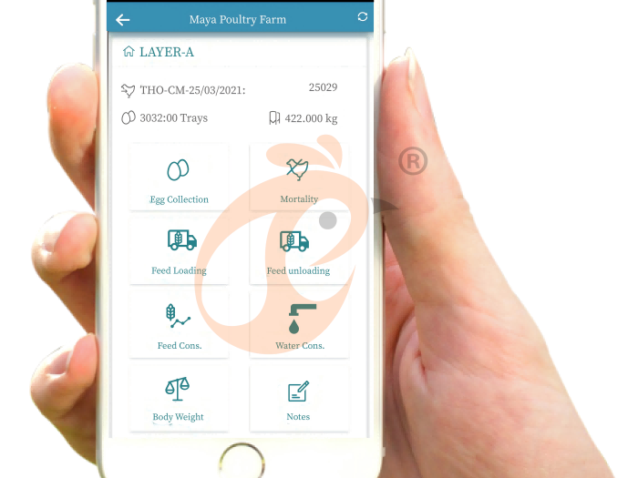
 IoT Poultry Farming System1. CO₂ 0–5,000 ppm range
2. NH₃ 0–100 ppm
3. RH ±3%
4. Thresholds in the 10–25 ppm range
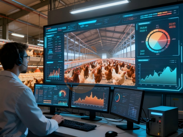
5. Reception /WhatsApp NO. : +8618830120193Read more Overall Structure IoT System In The Farm1. Breeding planning framework
2. CCTV
3. Poultry digital platform - comprehensive large screen
4. Alarm management
5. Reception /WhatsApp NO. : +8618830120193Read more Poultry House Environmental Control Smart IoT System1. Precision ventilation
2. Full site equipment control
3. Self diagnosis alarm system
4. European standard hardware
5. Reception /WhatsApp NO. : +8618830120193Read more

Contact us
Phone(whatsapp No. ):
E-mail:
Office 1 (Hong Kong):
Flat/RM A, 15/F, ManlyCommercial Building 15 Soy Street, Mong Kok
Office 2 (China Mainland):
Flat/RM 2416, 24/F, Runxing Building, Youyi Nan Street, Shijiazhuang City, Hebei Province